torsdag 18 december 2014

Minima QRP BFO and Mixer


I started with the BFO, put in an inductor 3,3 uH with one trimmer CT5 to minimum c, frequencies was 20,003 MHz, I tray to put in 2N7000 to connect the other trimmer CT4 butt F go 2-3 kHz lower without fet switched on. I try BA482 in serie to ground it only lower the frequency a few hundred Hz. Turning on the diod i found a value 2,2k to 4,7k will be fine, frequency is 19,995 MHz.

Dc is  T5:e = 5,6V T6:e = 5,2V it means 11 mA to the BFO. I winding the T3 6.5 turn trifilare on BN43–2402. Then time to do diode matching. see Diode... i think 2,2k to 12V is to mutch current 6mA, it take to long time to stabelesise.
The BFO gives 1,5Vp-p on C27 with no load. 600 mVp-p @ 50 ohm. I can now hare a IF 20MHz 1mV in to C38 also see 20MHz signal on osciloscope when tx and audio to mic amplifier.

Next its time for Bi-direction-amplifier.

Marry Christmas and a Good New Year, 

de SM4HNG Leif.

onsdag 3 december 2014


Minima QRP Transceiver The Audio part.


AF Amp

After reading on the freelists i decide to test the audio amplifier, because there was lot of ides to change the design i have LM380 and LM386 in the box. The original amplifier could give around 600mV rms over 8 ohm before clipping. The LM386 could give 2,8V rms over 8 ohm P = U*U/R = 2,8*2,8/8 ~ 1W, LM380 give less power.


47 uF out. -3dB @ 200 Hz, 0 dB @ 100 kHz
5 mA no input signal.
135 mA @ 1 W out.
input 150 mVrms  @ 2,8Vrms  out.

Pre Amplifier

Max out 940 mV rms before clipping. Around 1 mV in. T16:c = 11V.
T15:c = 8,2V , T15:e = 6,4V, Around 2 mA current.

Mic Amplifier

30 mV in around 40 mV rms out.  -3dB @ 20 Hz  -3 dB @ 10 kHz. there is a little maxi-ma @ 200 Hz around + 5-6 dB. T13.e = 1.5V T13:c = 5.1 V must be 7 mA.

Side Tone

Wen tone on gives around 100mV @ max volym on speaker output, Tx monitoring.
Around 1 mV @ C28 modulator. T17:c = 6,7V T17:e = 0,27V.


Next it is time to do the BFO, stay tuned SM4HNG, I relay like this building the Minima


söndag 16 november 2014


1.8" TFT LCD Display module ST7735S 128x160


The color on the TFT i not correct on this photo for same reason, sorry for that.
Just use level converter 5V -> 3,3 V 5 wires, CS, RESET, D/C, SCK and SDA.
Try the TFT sw in aurdino library Guide/TFT.

Next time i must find out if it is fast enough for S-meter update in next radio.
I am glad it works fine.


Minima main board started


The T/R switch is done. 5mA in Rx mode 45mA in Tx mode.
CW-Gen is done. 1mA when it is turned on. Output 10mV 720 Hz.

Tx/Rx, low = Tx  high = Rx, It is working ok if I/O is 3,3V.
CW-Gen if I/O is 3,3V R37 must be a lower value 47k > 27k, check T17c 6V.

Not much more to say about this.
The audio was to low for driving a speaker 140 m. So i must find a modification, i order some IC to tray. Next modification is to skip K2 LSB/USB relay.

The rest of the board will be the original design.


fredag 7 november 2014


QRP MINIMA DIGITAL BOARD


A complete logic to a all-band sw transceiver.
55 cm2   115 mA       Lo included  10 MHz - 260 MHz   around +16 dBm out.
I use a Spark-Fun Breakout board, i do not have RS232 on my computers.
I don't think the the pcb was aimed for adapt directly back of the lcd, but i find it possibility to do that, no wires just connectors.

I am really glad i came in to this project, Minima.
I used the test for LCD and I/O from AE5PH a few minutes after ended the soldering all is completed tested. I program in 10MHz, 3,75+20, 17.2 +20?   and 28.4+20 MHz for test.

I spend last weekend to measure the spurious, output level, and later phase noise.
I started this blog with the DDS-60 so i compared this to the Si570 unit.


Si 570 was around +16 dBm from 10MHz - 260 MHz. (10 dB atten to instrument)
DDS60 was 8.5 - 6 dBm out, 10 - 48.4 MHz

I use my home-breve spectrum analyzer.


And here is some phase nose measurements.


Si570  f = 10 MHz, Fnoise = 149dBc @ 10 kHz offset.
Si570  f = 23,75 MHz, Fnoise = 145dBc @ 10 kHz offset.
Si570  f = 37,2 MHz, Fnoise = 138dBc @ 10 kHz offset.
Si570  f = 48.4 MHz, Fnoise = 138dBc @ 10 kHz offset.
Si570  f = 144,3 MHz, Fnoise = 129dBc @ 10 kHz offset.

i think it is a relay good value.

DDS60 f = 23,75 MHz , Fnoise = 123 dBc @ 200-300kHz offset.

Here is the spurious list for Si570 @ 23.75 MHz

374665,-105.567
2.97076e+006,-105.015
3.30659e+006,-84.054
3.48848e+006,-105.268
4.47881e+006,-101.74
Nice values.

Here is the spurious list for DDS60 @ 23.75 MHz
432.174,-104.615
651.559,-105.865
866.931,-107.598
8217.29,-106.33
16483.7,-91.9783
19704.9,-94.6973
33065.9,-91.1369
38828.2,-93.0068
40964.1,-98.8106
48969.1,-78.3117
65155.9,-91.3816
83652.8,-84.6034
100000,-81.2614
115349,-84.2683
148096,-82.02
180225,-83.4377
197049,-79.2568
227295,-80.9892
248513,-71.561
297076,-77.092
342676,-72.7429
395275,-80.2696
424529,-80.6772
447881,-75.4794
545047,-80.7331
712382,-75.0742
738273,-74.7648
836528,-76.63
1.23886e+006,-75.5836


I also check the Output Z.
Si570 was 13 ohm  from 10MHz - 150MHz.
DDS60 was close to 50 ohm at 10 MHz and little higher @ 48.4 MHz.

I have never test so mutch on a LO signal, i enjoy to build and measure. 
No i lock forward to start with the main board next weekend.

This is the schematic for this PCB.


Thanks to Ashhar Farhan the designer.  
Thomas Sarlandie driver for Si570.
PP2KR Kleibe PCB-Maker, tanks a lot.


måndag 20 oktober 2014

QRP Minima


How i meat Minima.


One morning i search for Si570 and Arduino i came to this side http://www.phonestack.com/farhan/minima.html
Thanks Ashhar Farhan, for this transceiver.

Then i was really curious on this project, and start search more information.
The main page for this is http://www.hfsignals.org/index.php/Main_Page.

After a while i came to this side PP2KR.
Then i could not resist to bye the PCB from Kleibe PP2KR, thanks a lot.

Hear are some more god presentation. Thomas KK6AHT.

Here ar more links.


Video   EA7KB 

Now i am waiting for components to start build the digital board. Get it up and running, measuring on Si570 compared to AD9851. I will put up result her stay tuned.


BR Leif


tisdag 14 oktober 2014


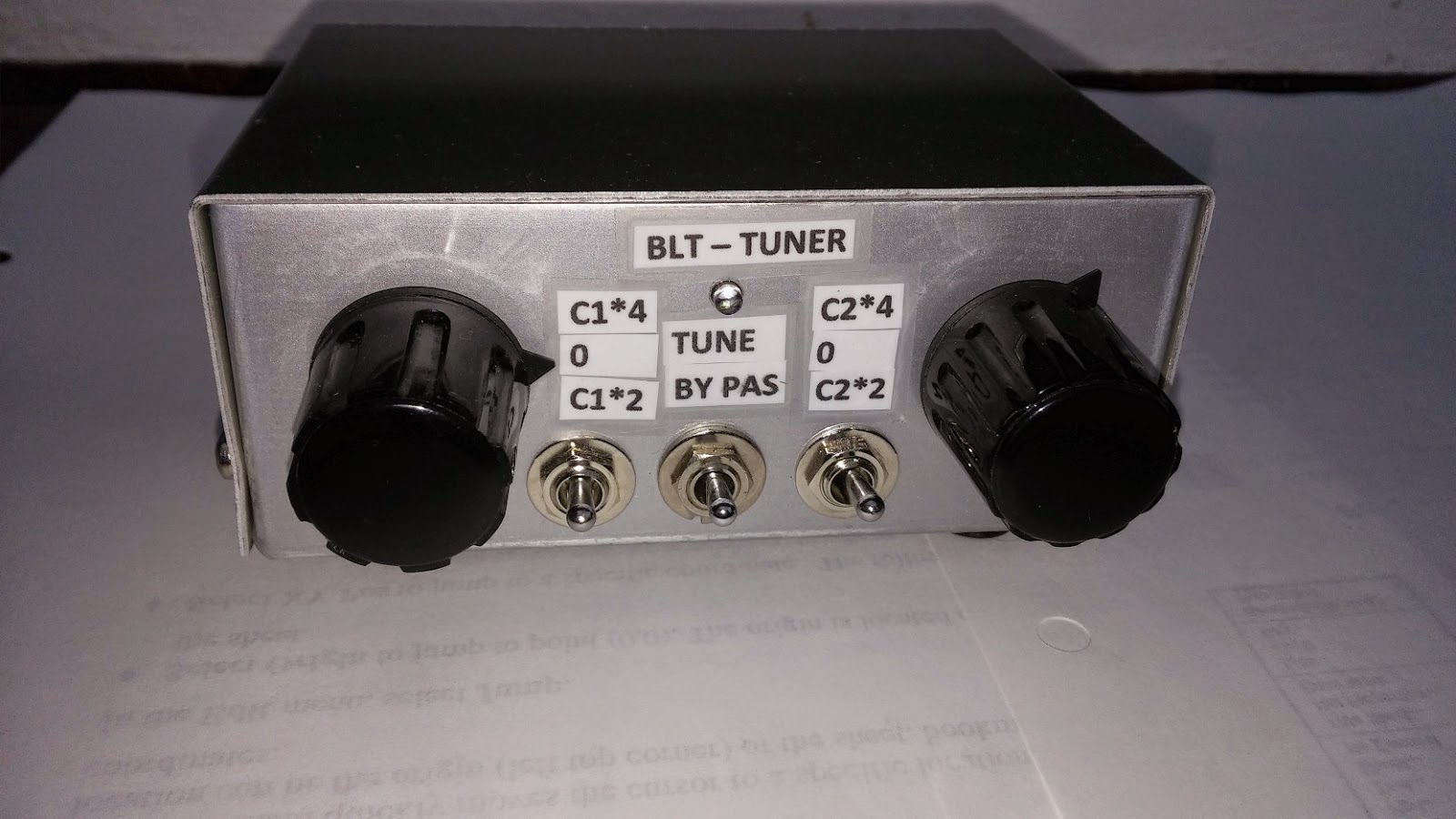
QRP - Tuners


This was mad a year ago but not marked. When i was on a QRP event i must take off the cover to understand how to use it, the labeling is now done. The inspire is from this tuner http://www.qrpkits.com/blt_plus.html


Later i came across this on ebay and order one kit. It looks ok, have only tested in lab-bench yet.


Hope it can be more used together with my QRP transceiver KN-Q10B, and the rig from this winter project, hopefully, stay tuned.


onsdag 8 oktober 2014


New Fox Receiver 80 M


This is a new board i receive a few weeks ago, Most off the resistors is now in place. I hope this will be the best receiver i have. The author is Bosse SM5CJW. I will experiment with the antenna for this receiver and see how it will preform. Compare ferrite -road and loop ant. I will put upp result hear, stay tuned.

fredag 3 oktober 2014


Fox Hunting


Long time as i write here. Fox hunting is one of may big interest. In May we run a fox hunting in Lindesberg Sweden. With this Transmitter, 5 pcs 1 with a broken antenna connector, this is now solved and hope to not happen again. Her is some data.

Frekvens                  144.765 MHz
Power                       1W
Lipo battery         11.1V 1200MAH 20C
Connector             DIN Start, Stop, Charging, Battery Check
                             Tele 3,5 Programming Com-port ttl)
Led                       Status of programming and battery
Programing           Modulation AM/FM
Number of fox
Call-sign at end of message
Competition time, test period, Tx interval. 

Screen shoot from the control soft-ware.


The software in transmitter and PC is made off may son Mattias.

We have no start planing for a 80m version this winter.
In Sweden all fox info is on http://www.pejla.se/


onsdag 30 april 2014


Transverter for 6m Ten Tec 1208


Found it on flea market in Eskilstuna.

Effter byte av en bränd transistor, fixat en olödning på balunen in till PA:t, samt en överlödning på balunen. Fungerade transvertern, men biasen var tvungen att byggas om. Har minskat dämpningen in så att den nu fungerar med 3-4W in ca 8W ut, Nu blir det dax att bygga en portabel 6M yagi 3 element.

de sm4hng

fredag 4 april 2014


Meas of the Capacitor Diode ISV149


This Can help me to get a working Xtal-filter. Haven't start this yet.

The Demodulate/Modulator SA612 is working. I need to adjust the LSB xtal, but i wait until the filter is finished to see where in frequency it should be pleased.  Also the level must be adjusted. No i will start solder the bi-direct amplifier.

måndag 24 mars 2014


Crystals


Lott of new experience this weekend. Using my new VNWA from http://www.sdr-kits.net/
I have measured Crystals from 2 - 32 MHz. i Have 10 HC-49S and 11 HC-49U 20 MHz. This was reserved for this project. Off the around 35 pics. i measured i put one in the trashcan. the is variation of Q and Rs in the samples. but the  HC-49S @ 20 MHz has a Q of 76000 - 90000 and should be okay.


A plot from the VNWA.

Amazing SW option included in VNWA sw.

I will later in this week hopefully mount lsb and usb crystal in the modulator/de-modulator.


fredag 21 mars 2014


QRP EDEN 20


Here is the backside of my MF. Now the Mic amplifier is there. Gain 13 - 33 dB. Current consumption 4.7 mA. Frequency response 3dB is 300Hz to 40 kHz. There is a filter between Mic amplifier and modulator. When i apply this it start oscillate at 1MHz but i solved it yesterday with 10 nF at gain potentiometer !
Next tonight i try to build the modulator SA612, and to finished i must desire MF frequency.

Murfe  has taken my oscilloscope, it is completely dark. So i leave the LF for now.

onsdag 12 mars 2014


 Here is the block diagram. It is then easier to understand what i am building. Here is some more links ho has inspired me.
SV1DJG  QRP and Homebrewing
G4FUI Photos tagged with eden9

The original is named EDEN 9.
Do anyone have a better ides of using LM380 SMD component prefer 1-2W out ?
Nex time is the mic amplifier.


söndag 9 mars 2014


MF EDEN 20

Next stepp was to bild a LF amplifier LM380. It works as it should ~ 650 mW @ 12V 8 ohm, 
or 1W @ 12V 4 ohm,  I = 15 mA no Audio  150 mA @ 1W out.  Gain 34 dB. Whit a litel 4 ohm speaker it sounds realy hard with 1 KHz ton. Frequency ressponce -3dB @ 165 Hz 0 dB @ 100 kHz.

On satterday i solder the preamplifier NE5534 clipping @ 250 mV out. The LM380 neds only 40 mV in
so this is ok Gain 28 dB  Frequency ressponce -3dB @  400 Hz and 2,4 kHz locks promising.

Together NE5534 + LM380 give a gain of 60dB measured.

Stay tuned next i put out a block diagram.


This is the homemade PCB for MF EDEN 20, i made it on to Thursday evning.  160*91 mm.
i use the cad ExpressPCB.

fredag 28 februari 2014

When i was searching on my calsign SM4HNG i found this Video from DG1BHA. It sounds it was a realy good aurora with 59A signals the distance JO79MD to JO73CE is 665km. Not bad on 144MHz.

Br Leif

fredag 21 februari 2014


Använder Aurdino för mina experiment, Har efter flera försök fått till DDS-60.
Så nu väntar MF på att bli till.
Jag kommer här publicera Mina QRP experiment. Håller på med en MF SSB/CW. Underlaget kommer från något som heter EDEN från Eden Valley Radio Society